
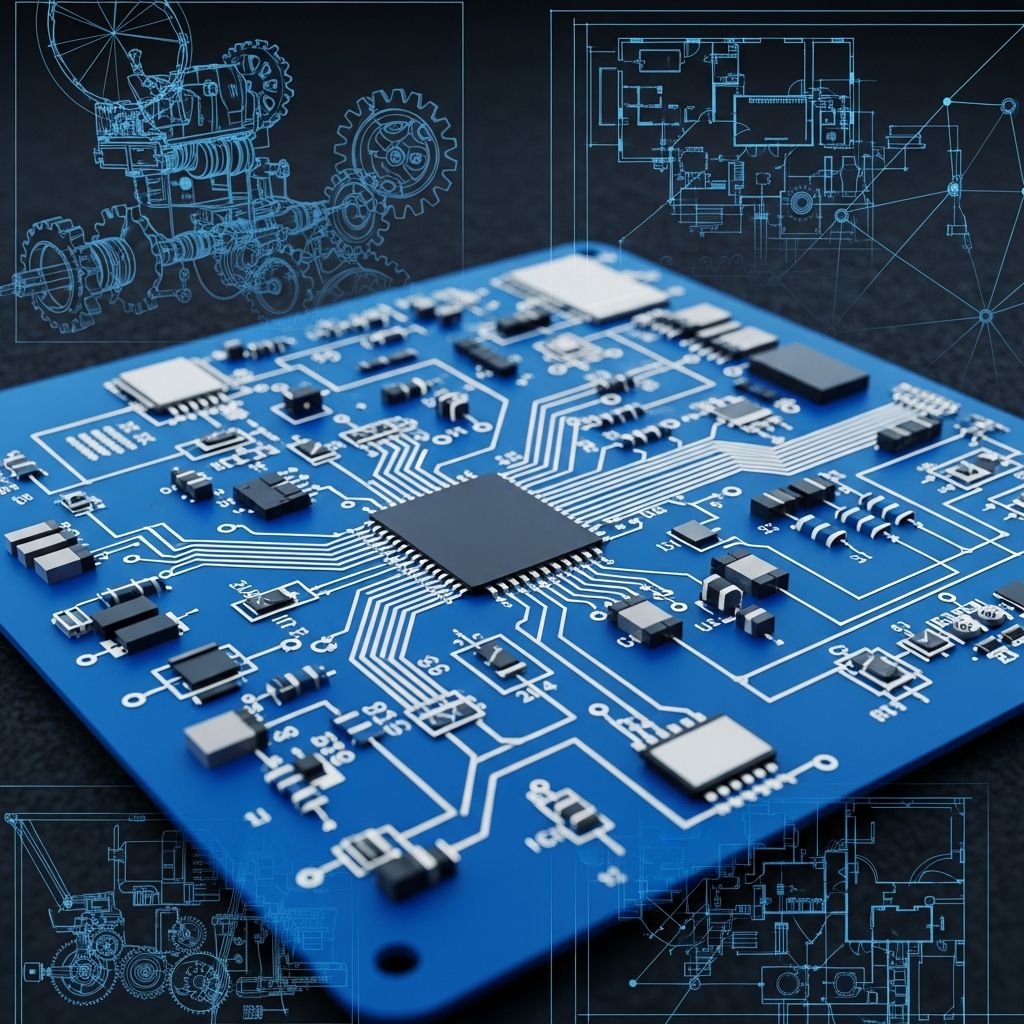
Schematic diagrams serve as the foundational visual language for engineers, representing complex systems through simplified symbols and connections rather than physical layouts. These diagrams prioritize logical flow and functionality, enabling clear communication of design intent across teams and disciplines.
Core Principles Behind Schematic Representations
At their heart, schematics abstract real-world components into standardized icons, stripping away unnecessary details like size, shape, or precise positioning. This approach allows focus on electrical paths, signal flow, and interactions. For instance, a resistor appears as a zigzag line regardless of its actual form, emphasizing its role in limiting current flow.
The primary elements include component symbols, nets (connection lines), and labels. Reference designators uniquely identify parts, while net names clarify multi-point connections, especially across diagram sheets. This structure ensures schematics remain readable even for intricate systems.
Why Abstraction Matters in System Design
Abstraction in schematics eliminates visual clutter, much like a subway map uses dots for stations instead of detailed buildings. It highlights functional relationships—such as how a transistor amplifies a signal—without distracting from physical constraints during initial design phases.
- Clarity: Symbols convey instant recognition for trained eyes.
- Scalability: Handles systems from simple circuits to power grids.
- Universality: Adheres to industry standards for global collaboration.
Distinguishing Schematics from Other Diagram Types
Schematics differ fundamentally from wiring diagrams or PCB layouts. While schematics define what connects to what logically, wiring diagrams show exact point-to-point paths for assembly, and layouts depict physical board traces.
| Diagram Type | Purpose | Focus | Example Use |
|---|---|---|---|
| Schematic | Logical connectivity | Symbols and nets | Circuit simulation |
| Wiring Diagram | Physical routing | Wire paths and harnesses | Assembly instructions |
| PCB Layout | Board fabrication | Traces and footprints | Manufacturing files |
| One-Line Diagram | Power system overview | Simplified phases | Grid planning |
This table illustrates how schematics act as the starting point, feeding into downstream physical designs.
Practical Applications Across Industries
Schematics underpin numerous fields, from consumer electronics to industrial automation. In PCB design, they guide component placement and trace routing, ensuring manufacturability.
Key uses include:
- Conceptualization: Brainstorming circuit ideas without hardware.
- Simulation: Testing behavior via software like SPICE before building.
- Documentation: Standardizing designs for revisions and compliance.
- Troubleshooting: Pinpointing faults by tracing logical paths.
- Training: Educating teams on system operation.
In power systems, one-line schematics compress three-phase details into single lines, simplifying substation or grid representations.
Electronics and Circuit Examples
Consider a basic power supply schematic: it depicts input voltage, regulation stages (e.g., capacitors, diodes), and output via symbols. Lines show current flow, with labels for voltages like +5V. Another example is an amplifier circuit, where input signals route through op-amps and feedback loops, abstracted for easy analysis.
Standards and Symbols: The Universal Language
Industry standards like IEEE 315 or IEC 60617 define symbols, ensuring consistency. Resistors use zigzags in American notation or rectangles in European styles, but connections remain unambiguous.
Modern tools enforce these via libraries, reducing errors. Net labels like “GND” or “VCC” bridge complex sheets, vital for multi-page designs.
Creating Schematics: Tools and Workflows
Traditionally hand-drawn, schematics now leverage EDA software for efficiency. Free tools like Scheme-It offer quick diagramming, while pro suites like Altium or KiCad integrate simulation and layout.
- Plan the Logic: Outline components and connections on paper.
- Select Symbols: Drag from libraries, assign values (e.g., 10kΩ resistor).
- Draw Nets: Connect pins, label junctions.
- Annotate: Add refs, notes, hierarchies.
- Verify: Run ERC (electrical rules check).
- Export: Generate netlists for PCB tools.
SOLIDWORKS Electrical extends this to P&ID, pneumatics, aiding multidisciplinary projects.
From Schematic to Prototype
A netlist extracts connectivity for PCB routers, transforming abstract logic into physical boards. This handover minimizes redesigns.
Advanced Uses: Simulation and Beyond
Schematics drive SPICE simulations, predicting performance under loads or faults. Tools generate netlists automatically, blending design with analysis.
In hydraulics or processes, block diagrams evolve into detailed schematics, optimizing flow without prototypes.
Challenges and Best Practices
Common pitfalls: ambiguous nets or non-standard symbols. Best practices include hierarchical sheets for modularity, power planes for clean distribution, and version control.
- Avoid crossover lines; use junctions or labels.
- Group related functions logically.
- Include bill of materials (BOM).
These ensure schematics remain living documents throughout product lifecycles.
Frequently Asked Questions (FAQs)
What is the main difference between a schematic and a wiring diagram?
Schematics show logical connections using symbols, while wiring diagrams depict physical wire runs for building or repair.
Can schematics be used for non-electrical systems?
Yes, they apply to hydraulics, pneumatics, and processes via adapted symbols.
What software is best for beginners to create schematics?
Tools like Scheme-It or KiCad provide free, intuitive interfaces with symbol libraries.
Why are standards important in schematic symbols?
They enable universal understanding, facilitating collaboration and compliance.
How do schematics aid in troubleshooting?
By mapping expected signals, engineers trace deviations logically.
References
- What is the Meaning of Schematic Diagram in PCB Design — A2Z EMS. 2023-05-15. https://www.a2zems.com/post/meaning-of-schematic-diagram
- Schematic – Wikipedia — Wikimedia Foundation. 2024-01-10. https://en.wikipedia.org/wiki/Schematic
- Schematic Diagram: Schematic Design, Standards, and Deliverables — NextPCB. 2023-08-22. https://www.nextpcb.com/blog/what-is-schematic-diagram
- What is Schematic Design? Definition and Examples — SOLIDWORKS. 2024-03-05. https://www.solidworks.com/solution/what-is-schematic-design
- The Schematic Diagram: A Basic Element of Circuit Design — Analog Devices. 2017-02-01. https://www.analog.com/en/resources/analog-dialogue/studentzone/studentzone-february-2017.html
- Schematic Diagrams – What Are They? — Ponoko. 2022-11-12. https://www.ponoko.com/guides/printed-circuit-boards-fabrication-assembly/meaning-of-a-schematic-diagram/
- How to Read a Schematic — SparkFun. 2023-07-18. https://learn.sparkfun.com/tutorials/how-to-read-a-schematic/all

- Integrated M.A. in Applied Linguistics, University of Hyderabad
- 5+ years in editorial, instructional, SEO, and research-based writing
Sneha is a relationships and lifestyle writer with a strong foundation in applied linguistics and certified training in relationship coaching. She brings over five years of writing experience to theskillvault, crafting thoughtful, research-driven content that empowers readers to build healthier relationships, boost emotional well-being, and embrace holistic living. Her writing and insights reflect the belief that beauty, happiness, and wellness…